

Battery Management System (BMS) Use Case
Battery Management System (BMS) – i5 Systems Delivered Use Case
This document describes a comprehensive Battery Management System (BMS) solution delivered by i5 Systems for an automotive OEM/Tier‑1 customer.
The project covers
- system architecture
- hardware–software co‑design
- embedded software development
- validation
- compliance with automotive functional safety and quality standards.
❖ Project Overview
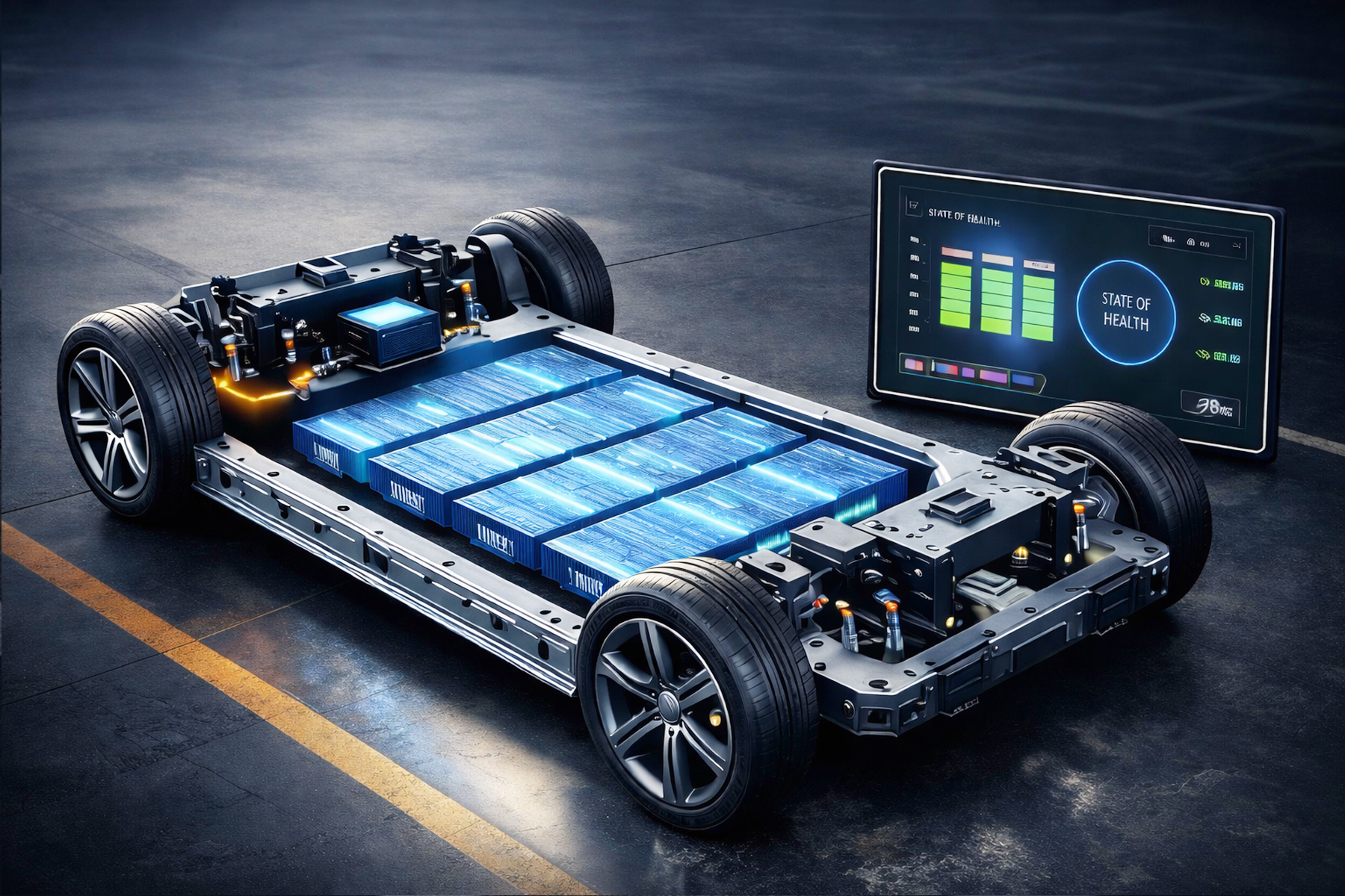
The objective of the project was to design, develop, and validate a scalable and production‑ready Battery Management System for electric and hybrid electric vehicles. The BMS ensures safe operation, optimal performance, and extended battery life through continuous monitoring, estimation, protection, and communication.
❖ System Scope
- Cell voltage, current, and temperature monitoring
- State of Charge (SoC) estimation
- State of Health (SoH) estimation
- Cell balancing (passive/ active)
- Fault detection and diagnostics
- Thermal protection and safety handling
- Vehicle network communication (CAN / CAN‑FD)
- Compliance with ISO 26262 and ASPICE
❖ BMS Architecture
The BMS architecture follows a layered approach:
- Battery Pack Level
- Module Level
- Cell Level
- Embedded Software Stack
- Communication & Diagnostics Layer
❖ Hardware Architecture
Key components include
- Battery Monitoring ICs (AFE – Analog Front End)
- Automotive‑grade MCU (ARM Cortex‑M series)
- Current sensing (shunt / Hall‑effect)
- Temperature sensors (NTC)
- High‑voltage isolation and protection circuits
- CAN transceiver
❖ Software Architecture
The software follows AUTOSAR‑Classic inspired layered architecture:
- Application Layer – SoC, SoH, balancing, diagnostics
- Service Layer – NVM, diagnostics, communication
- ECU Abstraction Layer
- MCAL
- RTOS (OSEK‑compliant)
❖ Core Algorithms
- SoC Estimation Coulomb counting + OCV correlation
- SoH Estimation Capacity fade and internal resistance modeling
- Cell Balancing Rule‑based and threshold‑based strategies
- Fault Detection Over/under voltage, over‑current, over‑temperature
❖ Communication & Diagnostics
- CAN / CAN‑FD communication with VCU
- UDS diagnostics (ISO 14229)
- DTC handling and fault memory
- Bootloader support for OTA updates
❖ Toolchain Used (i5 Systems)
- MATLAB / Simulink – algorithm modeling
- Embedded C / C++
- AUTOSAR configuration tools
- Vector CANoe / CANalyzer
- Lauterbach TRACE32
- TESSY – unit testing and coverage
- Jenkins – CI/CD
- Git / GitLab
❖ Development Workflow
- 01 Requirement analysis and system specification
- 02 Model‑based design and algorithm validation
- 03 Embedded software development
- 04 Unit testing and static analysis
- 05 Integration testing
- 06 HIL testing
- 07 Vehicle‑level validation
❖ Testing & Validation
- Unit Testing (TESSY)
- SIL & MIL testing
- HIL testing using dSPACE
- Fault injection testing
- Regression testing through CI
❖ Functional Safety & Quality
- ISO 26262 ASIL‑C compliance
- ASPICE Level 2 alignment
- FMEA and FMEDA
- Safety mechanisms and watchdogs
❖ Key Outcomes
- Robust and scalable BMS platform
- Improved battery safety and life time
- Reduced validation effort through automation
- Production‑ready software with OEM acceptance
❖ i5 Systems Value Proposition
i5 Systems delivered an end‑to‑end BMS solution covering architecture, development, testing, and compliance.
The engagement demonstrated i5’s strength in automotive embedded systems, model‑based design, and safety‑critical software development.